Electronics / Controllers: August 2010 Archives


Here's some simple code for the Seeeduino Stalker that can optionally reset the RTC and then prints the current time. It's not well-speced but the Stalker uses the standard DS-1307 real-time clock (RTC) so all the routines that use that library should just work plug-n-play:


#include <Wire.h>

#include "Time.h"
#include "DS1307RTC.h"

void setup() {
Serial.begin(9600);

// the next two lines can be removed if the RTC has been set
// setTime(6,51,0,6,8,10);
// set time to 17:05:00 1 Mar 2010 (see below)
// RTC.set(now()); // set the RTC to the current time (set in the previous line)

// format for setting time - setTime(hr,min,sec,day,month,yr);

setSyncProvider(RTC.get); // the function to get the time from the RTC

}

void loop() {
Serial.print( "The time is ");
 
Serial.print( year() );
Serial.write('/');
 
Serial.print( month() );
Serial.write('/');

Serial.print( day() );
Serial.write(' ');
 
Serial.print( hour() );
Serial.write(':');

Serial.print( minute() );
Serial.write(':');

Serial.println( second() );

}

Just a note to myself: the power connector on the Seeeduino (Arduino clones) is a JST XHP-2 connector.  It's not indicated on the specs.

seeeduino2123.jpg

This is connector #5 on the photo above.

I wanted to hook up a HD44780 LCD panel to my computer to use as a display via the LCD Smartie program.   The HD44780 displays are quite cheap on ebay (~$10) but the dedicated LCD displays that are sold for use with LCD Smartie are quite expensive (~$30).

In the spirit of hacking, I wanted to make my own hookup since I have plenty of HD44780 displays lying around because of my Arduino work.

The LCD Smartie site has a page showing the hookup from the DB25 parallel port on the rear of your computer to an HD44780.


lcd44780.gif

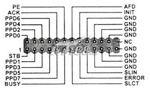
However, my cheapo Biostar motherboard doesn't have a rear DB25, only a 25 pin JPRNT1  header (a 2x13 male pin header) on the motherboard itself.  And surprisingly, there isn't any information on the web what the pinout on the JPRNT1 header is.  After much scrounging, I finally found a cached version of a single moribund  site that had the info:
 

ParallelPortHeader.png

Comparing with the DB25 layout, it looks like there is a 1:1 correspondence with the pins on the header and the pins on the cable, with the exception that the JPRNT1 header is 2x13 and not 13+12.  If you look at the header above, the numbers go:

2 4 6 8 10 12 14 16 18 20 22 24 nc
1 3 5 7 9 11 13 15 17 19 21 23 25


ParallelPort.gif

Just so that this info doesn't disappear from the ether, I'm keeping things cached here.

About this Archive

This page is a archive of entries in the Electronics / Controllers category from August 2010.

Electronics / Controllers: April 2010 is the previous archive.

Electronics / Controllers: January 2011 is the next archive.

Find recent content on the main index or look in the archives to find all content.